)
)
Why a Lego schedule board?
The recent warnings about Lego’s profitability would be even starker if not for 3 SIDED CUBE…
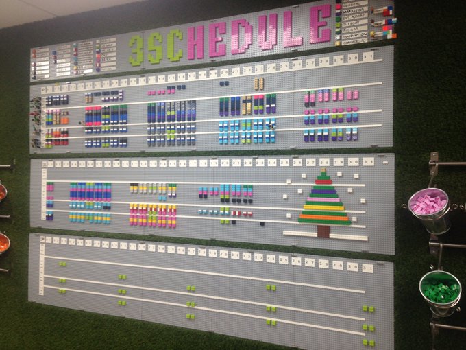
Over the last two years, we have amassed a vast quantity of Lego avatars, boards and blocks, with the goal of giving our previously inscrutable and spreadsheet-based schedule a more physical (and fun) presence.
Comprising thousands of bricks, our Lego schedule takes centre stage on one of the main walls as you enter the office, and is impossible to miss: every week a parliament of developers and PM’s gather round it, to democratically discuss and agree on the logistics of our upcoming workload.
The problem?
Despite the added transparency and visibility that comes from having this physical board, there are still a few issues that arise due to it no longer having a digital counterpart.
Firstly, there is no audit log – if someone moves a brick, we rely on the collective memory of our team to recall when, why and by whom this was done. Secondly, we also miss being able to integrate the schedule with other services: as a developer, I will not be automatically alerted if my schedule changes, and can’t view it remotely unless I access the webcam.
For these reasons, I spent my week of Innovation Time attempting to automatically digitise the schedule board using computer vision.
But what is computer vision?
Firstly, computer vision is often interpreted as being synonyms to object recognition. This is not the case. In fact, computer vision actually does a lot more in terms of analysing pictures… It’s an attempt to replicate or re-create human vision.
This means that there are deeper levels of analysis as computer vision using a kind of perception to take different factors into account. For example with the use of thermal imaging, temperature sensors or motion sensors to get a full picture of the scene it’s capturing.
However replicating human vision, as you can probably imagine, is no simple task.
Take a look at the video below for some examples of computer vision in the real world.
The challenges of using computer vision.
At any time, there are around twenty different production team members who are scheduled morning and afternoon for every weekday over a period of four months (each month has its own board).
Twenty different colours of Lego block are used to differentiate between projects, and these blocks appear in well-defined places within each board corresponding to the intersection between a developer (row) and day of the month (column).
All in all, this means there are around 3,000 regions within the board at which a distinct block could appear.
We can barely come up with a working definition of how our minds work, much less how to simulate it. Devin Coldewey
To keep things simple, for my initial attempt I chose to focus only on categorising the colour of each block (e.g. orange), rather than working out the project that colour is associated with (which would involve deciphering the legend in the top corner).
For practical reasons, the schedule would be read in from a webcam attached to the ceiling. Key challenges in reading the schedule would be:
Correcting for the perspective of the webcam, to make detecting blocks easier.
Finding each of the boards, and overlaying a grid so we can identify each of the bricks within it.
Distinguishing between differently coloured blocks, some of which are very similarly coloured.
To process the images of the schedule board, I used a piece of computer vision software from MATLAB, which makes prototyping computer vision workflows really simple.
How I digitised our Lego schedule board.
1) Finding the board.
Our first and most important job is to work out where in the image the boards are.
If we can do this accurately, we can then go on to work out the positions of individual bricks within the boards. A typical image of the schedule board is again shown below.
)
As can be seen from the image, all the boards are light grey, and the backdrop is largely green. This makes the task of separating the bit we are interested in somewhat easier.
For this reason, as an initial step, we process the raw image so that all the suitably grey pixels are highlighted. This step simplifies things somewhat, as it means we can remove irrelevant (at this stage) colour information, and focus on a simple binary image of white and black, where white represents a greyish pixel.
)
Afterwards, we can see that this step has largely picked out the boards. However, there are a few imperfections. Clearly, some things that are not Lego boards have been picked out, such as the silver buckets on the right-hand side of the bucket. Also, even though Lego’s diligent production processes have ensured the boards are uniformly grey, not all the pixels that “belong” to the boards have been picked out. This is due to differences in shading and illumination and is particularly apparent on the bottom-most board.
To correct these irregularities, I performed a binary image operation called morphological opening, which essentially spreads each white pixel a small distance into its neighbours to form a new, larger, region of white pixels — with holes and imperfections removed — before then eroding the entirety of this newly formed region so that it is contained within its original bounds — but with internal imperfections still removed. This results in an image like the one below:
)
Now, the area of each connected binary region is measured, and the four largest ones (that hopefully correspond to boards) are kept, and all others removed. Finally, we fill in any irregularities around the edges using some more morphological operations, to end up with the final binary image identifying the location of the boards.
)
It turns out**,** that because this process is based on simple assumptions (the boards are grey, the boards dominate the image, the background is not grey) it is also very robust, and works in a large variety of camera angles and lighting conditions. Robustness is desirable as it means we avoid having to recalibrate the detector every time we move the camera, or turn on the lights!
2) Fixing the camera angle.
Having located the boards, we are now ready to split them up into small brick-shaped regions. This is complicated slightly by the camera perspective – the boards are not orthogonal to the camera, and the boards at the bottom are smaller due to being further away from the ceiling-mounted camera. This means each brick is a different size and shape. It would make subsequent processing simpler if we could correct for this effect so that the board is oriented in a predictable way, and the bricks can be processed uniformly, regardless of where they are positioned.
In fact, as we know the exact dimensions of the boards and their relative position from each other, we can do this by discovering a transformation between the image coordinates and the real-world equivalents. This is known as image registration. The most convenient points to work with for this purpose are the top-left, top-right, bottom-left, and bottom-right corners of the board. We find these by running an edge detector over the binary image of the detected boards to get something like the following.
)
Next, we detect the dominant straight lines within this edge image, using a Hough transform, which is a well-established way of finding simple shapes inside binary images. All lines shorter than a certain length are removed, and then all lines are removed that are not the furthest up, down, left, or right. This leaves four lines, two horizontal and two vertical, and the corners of the boards can be found by calculating the intersection points of these lines using standard formulae. The lines detected for the edge image above are shown below:
)
To register the image so it is head-on, it is then intuitively a case of “stretching” out the above image so that the green lines are vertical, and the red lines are horizontal. In practice this involves calculating a transformation matrix using the four corner points we calculated. This gives a registered image like the following:
You can see that the top left and top right regions are now black, as these regions were not captured in the original image. Detecting the brick colours is now just a case of overlaying a uniform grid over each board and classifying the colour inside.
3) Identifying different Lego bricks.
Given that we know each board is 48 by 48 Lego bricks in height and width, and each month is formed from 5 of these boards, we can precisely overlay a grid over our schedule. In fact, we are only interested in some of these bricks, the ones at the intersection of an employee (a row) and a day (a column).
)
By manually labelling the bricks in a few example boards, we can establish a “ground truth” that can be used in a supervised learning setting to train a classifier based on each block’s pixel values. The classifier can then be used to predict the colour value of new, unseen bricks! Using machine learning in this way approximately halves the error rate from naively classifying each block based on simple colour distance. An example of a resulting classification is below:
)
There are a few errors, but on the whole, it does an ok job. It seems to get confused by grey-ish coloured bricks, and shadows and the underlying cause of these errors weren’t easily fixable in the time I had remaining on the project, so I decided to stop development here and come back to improve reliability in the future.
The future of our Lego schedule board?
By the end of the week, I had made something capable of reading the schedule board and detecting the brick colours to a reasonable degree of accuracy. The final product would need to be close to 100% accurate. The main reasons for misclassifications were:
Slight imperfections in the grid overlay, caused by the board not being perfectly straight, and perspective effects from the camera.
Very similarly coloured blocks.
My plan is to improve the grid overlay by using a UV marker (or similar) to mark out known locations within each month, which should then make the resulting grid more accurate.
Do you have any other suggestions?
Published on 6 April 2018, last updated on 10 April 2019